Many drivers have asked the same simple question,” What is the LS Main Cap Torque Sequence“? It’s an essential component in the process of assembling the engine.
You’ve completed a lengthy trip and want to repair your engine. You have gathered the tools you need and started removing your engine.
But you’re stuck while trying to put the engine parts together.
It’s not just you. Many drivers are facing the same issue when it comes to the cap sequence. Keep reading, and you’ll be able to figure out what to do.
What are the LS Main Cap Torque Sequence Specifications?
If we plan to build the engine, we must know specific details, such as the proper torque sequence and the steps to adjust the torque angle.
Also, we must know the torque specifications of the cap and rod torque specifications. We will examine all the relevant information and show you how to install the engine parts.
What is The Principal Cap Torque Sequence?
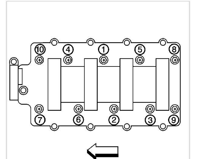
We should follow the correct sequence when we tighten outside bolts or internal bolts. With this, the engine will operate, and its life span may be reduced.
Check the following diagram for the torque sequence for the LS.
What are the LS Main Cap Torque Specifications?
We don’t just require the primary torque sequence for the cap. We also have to be aware of the torque specifications. We should keep our nuts, fasteners, and bolts tight enough to draw or make them loose.
In either case, it could cause the engine to perform inefficiently and decrease its life span.
The torque specification for the main cap’s inner excellent bolts is 15 pounds. Also, we must utilize our angle gauges to tighten these inner main bolts to 80 degrees.
The leading cap’s outer studs’ final passage is tightened to 15 lbs, and the angle is supposed to be 53 degrees.
What are the L Connecting Rod Torque Specifications?
When tightening the bolts on connecting rods, be aware that torque must be at least 15 pounds. Make sure to twist each bolt by an additional 75 degrees before using the gauge for torque angles.
What is the LS Bolt Torque Rear Cover Torque?
However you do, when assembling the engine, it is necessary to follow the steps of installing the cover on the rear.
Specific steps require us to know the bolt’s torque, which is essential to keep the engine parts in the correct position.
Before tightening the bolt that covers the rear of the block to before tightening the rear cover bolt to 18 Ft Lb, use a tool for alignment of the cover to ensure that the seal is aligned to those rails that the block’s oil is. Additionally, we offer 15-foot front bolts for cover.
What are 5.3 Flexplate Torque Specifications?
Its Flexplate bolts or Flywheel’s first step in the sequence are 15 ft-lbs. The second bolts for the second pass are 37 ft-lbs. The final pass is 74 feet lbs.
Make sure to align the hole in the Flywheel or flexplate to the hole on the back of your crankshaft.
Secure the bolts of the engine flywheel from the locker to the threads using the torque listed above.
Also, we must adhere to the procedure shown in the diagram. After that, repeat for the next pass and finally the final one of 74 ft-lbs.
What is Gen 3. 5.3 Head Bolt Torque Specs?
Another crucial component of the engine during assembly is the installation of bolts and cylinder heads. If you are using M11x 2.0 1.5 x 155.5 and M11 2.0 x 2.0 101.0 101.0 bolts, they should be adjusted to 22 ft-lbs on the initial pass.
Then, we employ the torque angle gauge to turn the 90-degree and 50-degree angles, respectively, during the second step.
To make M8x 1.25 x 46.0, we tighten the bolts numbered 11 to 15, 15 to 22, and ft-lbs. There is no requirement to make an angle for these bolts. Additionally, they are solid. The torque on cylinder head studs is around 80 ft-lb.
What is the LS Cam Plate Torque?
When putting in the retainer plate for the camshaft plate, it is necessary to set four bolts and torque up to 18 ft-lbs.
If we use bolts for the camshaft’s retainer plate with TORX heads, the torque spec must be 11 ft. lbs.
What are the most important steps to follow for Engine Assembly?
We have all the required information to build a car’s engine. Consider inquiring about additional issues related to the engine assembly.
The steps are complex and require technology skills to complete the job. Taking your vehicle to a mechanic is the best option if you need more time.
Install the Main Bolts and Bearing Caps
Put the block engine on its foundation upside down. Reinstall all block plugs with screws and that coolant connector, as well as the oil gallery.
Place the front galley oil plugs into the block’s driver side.
Install the thread locker around its circular shape and secure it using the flathead punch. The plug for the rear oil gallery and main bearings can now be implemented.
Upper-bearing shells should be installed in the block, whereas those bearings on the bottom must be placed inside the caps used for mains.
Make sure you place the thrust-bearing shells into the center-bearing block.
Check your upper shells of bearings are adequately lubricated. Put the crank into the block and hold the crankshaft between the snout and flange on the back.
After you have lubricated the lower shells, place the main caps on the bearings and ensure that each cap is inserted precisely where it is supposed to be.
Join Pistons To Connecting Rods
After putting in the main caps on the bearings, we tighten the internal and outer main cap bolts according to the diagram above.
It is crucial to adhere to the primary torque sequence and specifications for your engine to function efficiently.
With the crankshaft installed now, we can attach the pistons to the connecting rods. rods. When we’ve got a rod to one end, we can apply clean oil to clean the friction surfaces within the piston and rod.
Move the pin along to the bores of the rod and then the piston until it reaches the clip on the piston.
Install Piston/Rod Assembly
It’s better to be equipped with a tool to turn the crank. If you don’t have the tools, we can install an existing crank bolt and use the 24mm wrench to turn the crankshaft rotation in the final assembly stage.
We now install the rod bearings that connect them. The lower attachment shell of the rod to the cap, and then the top one to the top of the rod.
To install the piston or rod into the ring compressor, move the engine onto its stand and then turn the crank until it is at the bottom dead center.
Begin by gently lubricating the skirt of the appropriate number rod assembly or piston and gently pushing the piston into the ring compressor sleeve by hand.
Install Camshaft
Then, we place the piston in the bore by securing the ring compressor against the table’s surface. We then tap the piston using a hammer that is rubber.
Then, we place the rod in the journal. Once that’s done, it is time to put the rod caps on.
The connection rod bolts using specifications and torque as described above. We now put in the crankshaft position sensor. Make sure to tighten the crankshaft position bolt to 18 ft-lbs.
Installation Oil Pump
The short-block building is finished! Relax and enjoy a relaxing break. The camshaft is now installed. Its front is identified by the sprocket’s location pin and bolt hole(s).
Install the cam until the journal bearings in the rear of the cam are resting upon the front bearings of your block.
The next step is to install the camshaft retainer plate, which must be installed in the same manner as previously described. Now is the time to put in the crankshaft key and sprocket.
A mallet made of rubber to insert the key into the keyway on the snout of the crankshaft. It is possible to slide it across the snout to install replacement sprockets from the market, and the key will rest entirely upon the crank.
After that, we can put the timing chain and the oil pump.
Rear Cover
Before putting in the cover at the rear before installing the rear cover, we need to install the pickup tube for the pump and tray for the oil deflector. Oil the pump’s input and O-ring hole by applying oil prior to inserting the tube for pickup.
The retainer bolt is torqued to 106 ft-lbs. The tray that deflects oil is torqued to 18 feet pounds.
We can now install our rear covers. Be careful when putting the cover on the rear of the block because the crank seal lips could quickly become misaligned.
This can cause an oil leak in the future. The bolts for the rear cover need to be torqued to 18 ft-lbs.
Cylinder Head and Bolts
It is necessary to put the front covers, the oil pan, and the camshaft sensor bolt in, after which we need to install the lever valve guide bolts and guide trays before the head of the cylinder.
Then, we put the head gasket onto the block and checked for an incompatibility recess on the gasket.
Verify that you are sure your deck’s surface is free of dirt. There are 15 cylinder head bolts that you can use; ten of them have a large dimension (M11). In addition, all the rest have smaller diameters (M8 thread).
To tighten M11 Head Bolts, for drawing the M11 Head, we pull the bolts 1-10 in order in the diagram up to 22 ft-lbs.
Then, we turn 90 degrees using angles. After locking all M11 bolts, use a hammer to tighten the M8 inner bolts in an order of 11 to 15 at a rate of 22 ft pounds.
Arms of rocker and Intake Manifold
The procedure is dependent on the type of rocker arms that we employ. The main thing to remember when setting up an adjustable valve is to reduce the lash adjusters.
When they do this, the nuts will help fix the nuts to the mounting.
Additionally, we will put in those valve covers, the oil pressure sensor, and the coolant air bolts for the bleed pipe. It is now possible to consider how to install the intake manifold.
The intake seals could slide through the grooves during the process. Ensure that they’re installed correctly before proceeding.
Remove the masking tape in the intake port. Clean the sealing surface, then put in the 11 ft-lb intake manifold bolts.
Flexplate
Before putting in the flexplate, inserting the fuel rails and the throttle body is necessary. Make sure to align the hole in the Flywheel or flexplate to the hole on the back of the crankshaft’s rear.
Inject the six bolts into the nut by affixing the thread locker on their threads. The torque should be 15 ft-lbs following the steps in the diagram below.
We’ll put in the harmonic damper at last, and the engine installation is nearly complete.
Conclusion
Check out the above diagram if you are searching for “What is the LS main torque sequence for cap.” You should follow this order unless the engine’s lifespan has been shorter.
The assembly of engines is a complex process and requires you to possess some knowledge. Otherwise, you must bring it to an expert mechanic.
Related topic: 6.0 powerstroke years to avoid